
The OSI model explained—with memory teasers
As an IT professional, chances are you’ve come across the phrase Please Do Not Throw Sausage Pizza Away while hearing about protocols, network design, and implementation issues.
How about Or Please Do Not Touch Steve’s Pet Alligator?
If these ring a bell then you’re on the right track: These are smart memory aids linked to the seven layers of the Open System Interconnection (OSI) model. The first letter of each word helps with knowing the layers’ order in the OSI model and identifying the layer itself.
But before we dig into the technicalities, let’s start with some basics about just what the OSI network model is.
What is the OSI model?
The OSI model is a conceptual model for understanding how data flows across and within networks. It was adopted as an international standard in 1984 following the merger of two models from the 1970s.
Primary computer and telecom companies used this model to break down device-to-device communication into seven layers. These seven layers act as a visual map to understand what’s going on in a networking system.
For IT professionals then and now, the OSI model means targeted troubleshooting made easy: instead of wasting hours deciphering problems, they can pinpoint issues linked to particular layers.
For network device vendors, application developers, and network engineers, the model means abstracting away complexity from device-to-device communication, by focusing on solving one problem at a time. As well, the model was developed to provide standardized networking protocols to avoid the use of devices that lack user-and application-friendliness.
The seven layers of the OSI model explained
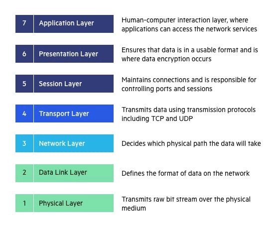
The seven layers of the OSI model from bottom to top are physical, data link, network, transport, session, presentation, and application.
Each layer in the OSI model performs specific functions interconnected to the layers above and below by offering services or support. The first three are mostly concerned with hardware and getting traffic to an end system from the network. The next four layers are software-related and complete the communication process in the end system.

Layer 1: the physical layer
As the foundational layer in the OSI model, the physical layer is responsible for providing a physical wired or wireless connection between network nodes (devices). It defines the media, connection, and signal type (whether analog or digital) to be used, and transmits that raw data as signals. All networking devices and specifications, such as radio frequencies and hardware, are defined at this layer. Examples of components at the physical layer include antennas, network interface cards (NIC), cabling, adapters, and pins.
The main functions of the physical layer are:
- Bit rate control and synchronization: The number of bits per second and bit synchronization are defined.
- Physical topology: How the devices are arranged within the network, whether bus, star, ring, mesh, etc.
- Transmission mode: Specifications that control data flow according to simplex, half-duplex, and full-duplex mode. Most, if not all, modern wired networks use full-duplex transmission modes.
- Physical attribute definition: Type of connector, pin arrangement, interface card, etc.
Layer 2: the data link layer
The data link layer (DLL) defines how networked media access the network, as well as ensuring that data coming from the physical layer is synchronized. This layer is also responsible for error detection from the physical layer.
Here, data bits are packaged into frames, combining raw data into bytes, and then these bytes are combined into frames that vary in size based on the specific Layer 2 protocol. Hardware on the other end of the communication node then receives the decoded frames from the receiving data link. The DLL is subdivided into two layers:
- Logical Link Control (LLC): Responsible for the flow control to ensure that frames are transmitted at the same speed between both sender and receiver to avoid a mismatch. A mismatch in speed can lead to data loss.
- Medium Access Control (MAC): The primary purpose of the MAC is brokering access to the physical medium that’s used to transmit data. This includes functions such as addressing, frame delimiting (identifying the start and ends of frames) and protecting against errors.
Layer 3: the network layer
The network layer takes care of data routing and handling data transmission from one network to another. It selects the shortest possible path from one host to another on different networks.
Once the packet is received from the DLL, the network layer identifies whether the packet is destined for the local host (in which case it’s sent up to a higher layer), is destined for a different host on the local network (in which case is sent back down to a lower layer), or is destined for a different network altogether, and in this case it does the necessary routing to the address contained in the frame.
In the standard TCP/IP model, this is done by implementing logical IP addressing and using routers for communication. Data going out are divided into packets which are then reassembled at the receiving end.
Examples of protocols at Layer 3 include Internet Protocol Version 4 (IPv4), Internet Protocol version 6 (IPv6), ICMP, and GRE.
Layer 4: the transport layer
The transport layer represents the first layer in the OSI model to model a true source-to-destination communication flow. While data transmitted at the transport layer can be connection-oriented (e.g., TCP) or connectionless (e.g., UDP), it’s most common that end-to-end delivery of error-free data packets occurs at this level.
If an error occurs during transmission, the transport layer makes the necessary resubmission request to get it through. Service port address, also known as a port address, is used in the end-to-end delivery to ensure the data reach the correct location.
Data coming from the session layer (Layer 5) is broken down into segments which are later reassembled on the receiving end.
While transmission control protocol (TCP) and user datagram protocol (UDP) are the two most common Layer 4 protocols, reliable data transmission is handled by TCP and is used along with a three-way handshake process and sequencing flow control.
Unreliable data transmission is associated with UDP; this doesn’t mean that all UDP traffic is unreliable, however, as there are layers above in the OSI model that may handle resolving the errors in UDP.
Other functions of the transport layer include:
- Establishing a virtual circuit
- Data realignment on the receiving end
- Connection multiplexing with port numbers
- Client-side identification
Layer 5: the session layer
When computers or other devices communicate, the session layer checks the network request to determine whether the resource is available in a local or remote system. A session is established if the proper network connection is available. Once the session ends, the session layer is responsible for terminating it.
The session layer can be seen as more of a housekeeping layer: opening communication channels, ensuring they remain open, managing communication synchronization, identifying full-duplex or half-duplex operations, authenticating communication, creating dialog units, and so on. It also uses checkpoints to manage data transfer and ensure that recovery can occur at the point of interruption the session interrupted.
Layer 6: the presentation layer
Applications are both semantic and syntax specific. Also known as the translation layer, the presentation layer ensures that the data are presented to the application in a format it understands. In allowing the application to read and understand its message, the presentation layer also does the necessary encryption and decryption for message security.
Other functions of this layer include:
- Data compression
- System-specific translation
- Data conversion
- Character code translation
- Graphics formatting
Layer 7: the application layer
Layer 7 is what end-users interact with daily. Through an interface connected to the network, the user can see data in a format that’s tailored to specific use and commands. Examples include file transfers, directory services, electronic mail, electronic messaging, and network data sharing. Protocols at the application layer are File Transfer Protocol (FTP), Simple Mail Transfer Protocol (SMTP) and Domain Name System (DNS), Hypertext Transfer Protocol (HTTP), and Simple Mail Transfer Protocol (SMTP).
Advantages and disadvantages of the OSI model
Pros
- It’s very specific. Looking for a problem at a particular level is much easier than trying to find what’s causing an issue across an entire network.
- It provides a standard for devices to follow and gives users more control over hardware and software.
- It’s well suited as a tool for generating any network topology.
- It provides a distinct separation of services, interfaces, and protocols.
- As a layered model, specific applications can be applied to a particular layer without affecting the entire network.
Cons
- Some network professionals view it as more of a conceptual model than a practical one.
- Service duplication in different layers makes it inefficient, slow, and costly.
- It doesn’t support parallel processes.
- It lacks protocol definition.
Uses of the OSI model explained
With the OSI network model considered by some as outdated and impractical, the question that pops up is usually: Why use it? Security and network development are the main reasons why savvy IT experts still bring out the OSI model to troubleshoot and communicate complex network challenges with one another:
- Troubleshooting: The OSI model allows IT professionals to logically break down complex network challenges into manageable tasks, thus providing checkpoints along the troubleshooting journey. If a user is having network performance problems, you can check the quality of the connection at Layer 1, Layer 2, Layer 3, etc. to narrow down the performance issue.
- Communication: While the majority of IT professionals are familiar with the TCP/IP internet model, there are other communication networks in the wild. Having the OSI model allows IT professionals to communicate with one another inconsistent and easily recognizable terms to reduce miscommunications.
OSI vs. TCP/IP
Despite the widespread knowledge of the OSI network model, it’s often compared to the 4-layer TCP/IP model. As an IT professional, it’s important that you understand the differences and similarities between these two models. After all, they’re not in competition but are related.
In the TCP/IP model, the application layer performs the function of the three higher-level (5, 6, 7) layers of the OSI model. Additionally, a network access layer in the TCP/IP model combines the function of two lower-level (1 and 2) layers in the OSI model and leaves sequencing and acknowledgment functions to the transport layer.
Why this major difference? Primarily because the OSI model was defined after much of the TCP/IP model was established. Rather than try and mold the OSI model to the 4-layer TCP/IP model, a more scalable 7-layer model was created.
Despite not catching on widely, the OSI model is still used today when referring to network architecture, and still appears as a possible question on certification tests (and maybe your next job interview?).
So be sure to remember Please Do Not Throw Sausage Pizza Away, so you can have a common networking language to engage with clients, vendors, and other network administrators.
